
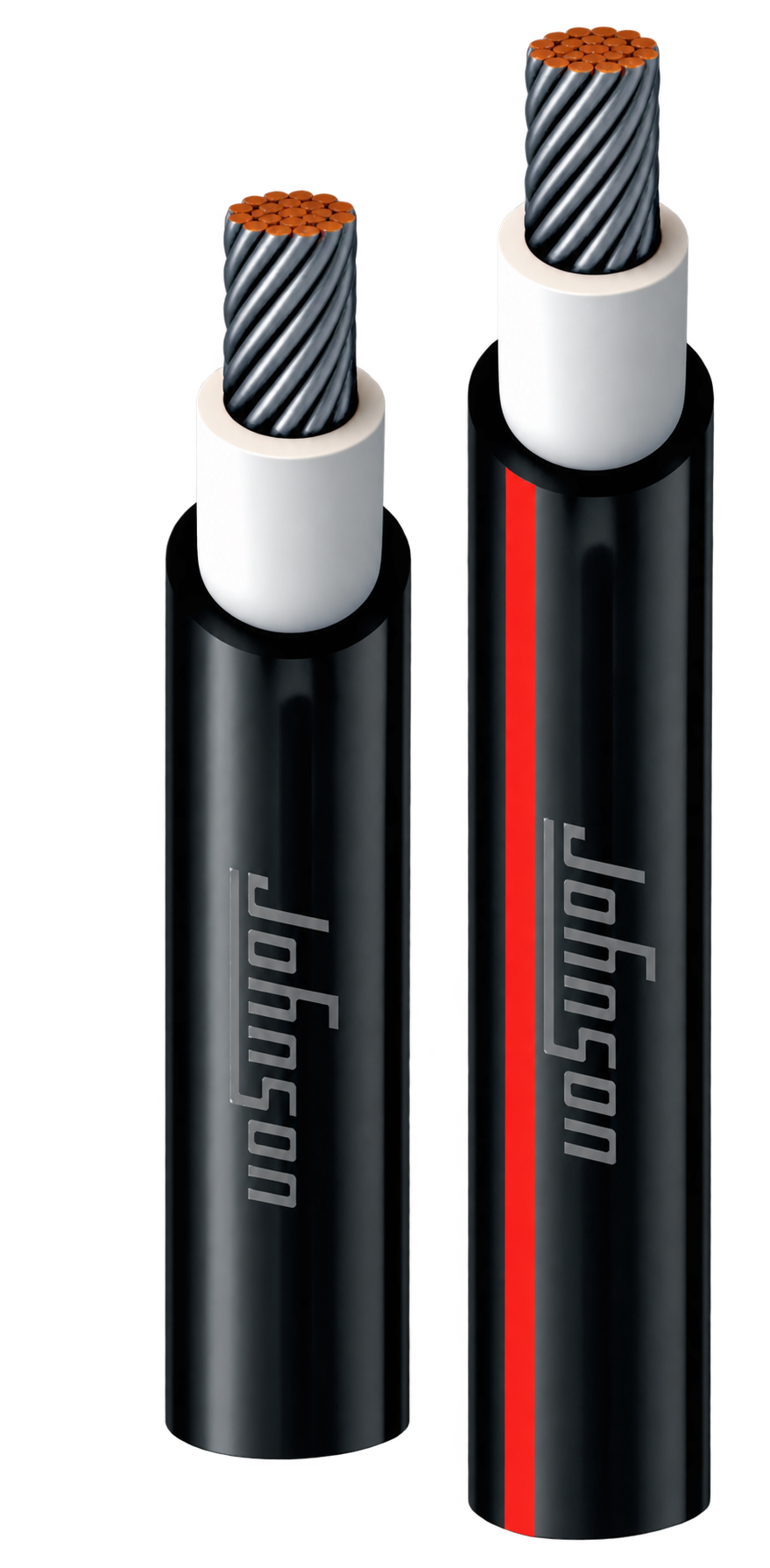
1 Core
Johnson Photovoltaic Solar Cable
XLPO Insulated & XLPO Sheathed Flexible Solar Cable
Application
Photovoltaic (Solar) Cables are specially designed for solar power systems, where photovoltaic modules convert solar energy into electrical energy. These cables ensure safe, efficient, and reliable transmission of power while withstanding demanding outdoor environmental conditions.
Operating Temp & Test Voltage
Temp Range: -40°C to +90°C | Test Voltage: 6.5 KV for 5 min (AC)
Available Colours
Core:
White / Natural
Sheath:
Black / Red
CABLE DESIGN
TECHNICAL STRUCTURE-
Tin Copper Conductor Flexible tinned copper conductor (IEC 60228)
-
Insulation Polyolefin copolymer halogen free fire retardant low smoke compound.
-
Sheath Highly weather & uv resistance, polyolefin copolymer halogen free fire retardant low smoke compound.
-
Mechanical Property (Insulation-XLPO HFFR) Tensile strength: 6.5 N/mm2 (Min.) According to EN 60811-1-1
Elongation: 125% (Min.) According to EN 60811-1-1 -
Mechanical Property (Sheath-XLPO HFFR) Tensile strength: 8.0 N/mm2 (Min.) according to EN 60811-1-1
Elongation: 125% (Min.) according to En 60811-1-1
Temp. Range: (-40°C to +90°C)
Test Voltage: 6.5 KV for 5 min (AC) -
Volume Resistivity Insulation (Electrical Property) EN 50395 1x10¹⁴ (min.) Ω-cm at 20°C Temp.
1x10¹¹ (min.) Ω-cm at 90 °C Temp.
FEATURES
PERFORMANCE & SAFETY- High thermal rating to withstand extreme temperatures.
- Specially designed to withstand extreme weather conditions.
- UV resistance according to HD 605/A1
- Flame retardant to IEC 60332-1-2
- Halogen free accordance with BS EN 50525-1
- Low smoke density accordance with IEC 61034-2
- Excellent abrasion and notch-resistant.
- High current-carrying capacity for efficient PV system performance.
- Sequential meter marking with brand name and cable size printed on the sheath for easy identification.
AVAILABLE COLOURS
Core Color:
Sheath Color:
|
Or as per customer requirement.
Technical Specifications
| NOMINAL CROSS SECTIONAL AREA mm² | NUMBER/ NOMINAL DIA OF WIRES (MAX) Number/mm | MIN. INSULATION THICKNESS mm | NOMINAL THICKNESS OF SHEATH mm | NOMINAL OVERALL DIMENSION mm | MAXIMUM DC RESISTANCE CONDUCTOR AT 20°C Ω/km | MAX. CURRENT CARRYING CAPACITY (AIR) Amps | MAX. CURRENT CARRYING CAPACITY (SURFACE) Amps |
|---|---|---|---|---|---|---|---|
| AS PER TUV 2PFG 1169/08.2007 (PV1-F) | |||||||
| 1 x 2.5 | 36/0.3 | 0.50 | 0.50 | 4.70 | 7.56 | 41 | 39 |
| 1 x 4 | 56/0.3 | 0.50 | 0.50 | 5.20 | 5.09 | 55 | 52 |
| 1 x 6 | 84/0.3 | 0.50 | 0.50 | 5.70 | 3.39 | 70 | 67 |
| AS PER TUV SPECIFICATION – EN 50618:2014 (H1Z2Z2-K) | |||||||
| 1 x 2.5 | 36/0.3 | 0.7 | 0.8 | 5.30 | 7.56 | 41 | 39 |
| 1 x 4 | 56/0.3 | 0.7 | 0.8 | 5.80 | 5.09 | 55 | 52 |
| 1 x 6 | 84/0.3 | 0.7 | 0.8 | 6.30 | 3.39 | 70 | 67 |
| 1 x 10 | 140/0.3 | 0.7 | 0.8 | 7.90 | 1.95 | 98 | 93 |
| 1 x 16 | 224/0.3 | 0.7 | 0.9 | 9.20 | 1.24 | 132 | 125 |
| 1 x 25 | 350/0.3 | 0.9 | 1.0 | 11.20 | 0.795 | 176 | 167 |
| 1 x 35 | 490/0.3 | 0.9 | 1.1 | 12.60 | 0.565 | 218 | 207 |
| 1 x 50 | 703/0.3 | 1.0 | 1.2 | 14.50 | 0.393 | 276 | 262 |
| 1 x 70 | 988/0.3 | 1.1 | 1.2 | 16.50 | 0.277 | 347 | 330 |
| 1 x 95 | 1349/0.3 | 1.1 | 1.3 | 18.70 | 0.21 | 416 | 395 |
| 1 x 120 | 608/0.5 | 1.2 | 1.3 | 21.00 | 0.164 | 488 | 464 |
Important Technical Notes
- NOTE: AT: AMBIENT TEMPERATURE
- TOLERANCE ON DIAMETER: 2.5 SQ MM TO 16 SQ MM +/-0.40 MM AND 25 SQ MM TO 120 SQ MM +/- 0.60 MM
- THE NO. OF STRAND & STRANDS DIAMETER SHALL BE SUCH THAT IT MEETS THE CONDUCTOR RESISTANCE AS PER RELEVANT STANDARD